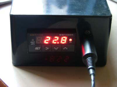
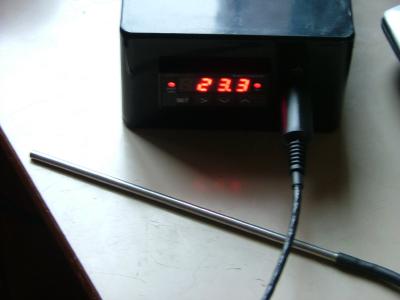
There are a number of occaisions in home brewing when having a device that can automatically control a mains powered heating element (or cooling device for that matter) is useful. My reason for putting this device together is to control my fermentation vessel heating mat so that during the winter, I can keep my fermenting wort at a nice steady temperature but other home brewers use similar devices to control heating elements in recirculating mash systems (HERMS systems etc).
The device shown here combines a number of off-the-shelf parts to achieve the aims set out above
Warning: Mains electricity is dangerous and you should only attempt to build one of these devices if you are completely confident that you are being safe or if you know a competent person who can double check your wiring. You have been Warned!
The heart of the regulator is an XMT7100 PID controller which I bought from eBay. These can be quite expensive and are therefore normally only used in industrial applications however they have dropped in price in recent years and they are available on eBay delivered direct from Hong Kong at reasonable rates. A PID controller is a sophisticated electronics device which can control an output based on a measured temperature. You certainly don’t need to understand how these devices work in order to successfully use them but if you are interested, the initials “PID” stand for: P = Proportional, I = Integral and D = Derivative. If you want to go further, these controllers are well documented in many places on the web and a good starting place is Wikipedia.
The PID controller has a built in mains rated relay but it is limited to switching loads of up to 3A. That would have been fine for my intended application but I might want to use this for other things in future so I decided that I would add an external solid state relay (SSR) instead. The advantage of using an SSR over a conventional mechanical relay is that there are no moving parts to wear out through repeated switching. The picture below shows a Crydom SSR. Somewhat confusingly, the connections are called ‘input’ and ‘output’ – but beware – the terminals called ‘output’ are the mains connections and the terminals called ‘input’ are the low voltage control connections.

So on to the interesting stuff…
The PID controller can take temperature measurement from several types of temperature sensor however the most commonly used sensors are either thermocouples (usually Type-K) or platinum resistance thermometers (PRTs) (usually PT100). The schematic diagrams below show the connections for both a Type-K thermocouple and a 3 wire PT100 sensor.
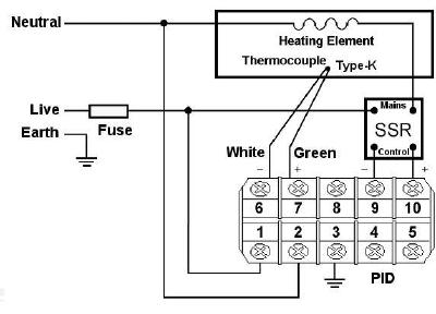
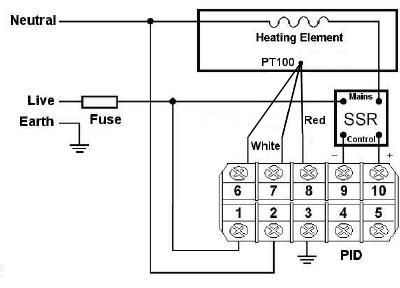
Some notes on sensors:
- The colour coding on your sensors may be different to those shown above but the colours shown are the current industry standards; if you have an older sensor then you may need to look up the colour coding.
- Thermocouples require careful attention when wiring up – if you extend the thermocouple wires, you MUST use the correct sort of thermocouple wire (the same at the thermocouple type) otherwise you will introduce measurement errors. Likewise, if you add thermocouple plugs and sockets, you MUST use the same type sockets as your thermocouple type to avoid measurement errors.
- PRTs come in 2 wire, 3 wire and 4 wire types. The diagram above shows a three wire sensor. If your sensor has more than three wires, you can still use it by connecting together wires of the same colour. Alternatively if you have a two wire sensor, you can link across the two XMT-7100 connections (6 and 7) – performance with a two wire sensor is poor though.
And now on to construction:
I decided to use a PT100 sensor in this device and wanted it to be detatchable therefore I connected it via a miniature DIN connector. I mounted the PID, SSR, MiniDIN connector and mains connectors in a black ABS enclosure. The two photos below show the internal wiring from two angles:
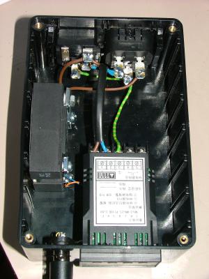
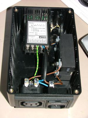
The photo below shows the front view with the MiniDIN socket for the sensor mounted next to the PID controller.
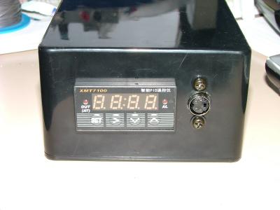
Having assembled the device, it was time to plug it in and configure the PID parameters. The XMT-7100 manualmanual is just about adequate when it comes to configuring the adjustable parameters. The photos below show the finished device in action.
