Over a year ago I decided I wanted to build a small Quadcopter. I bought some Hexatronic 5 gram brushless DC motors (HXM1400-2000) and some 6A Turnigy speed controllers. I designed a lightweight aluminium frame on CAD and did some research on how to stabilise it and control the four motors.
I came across an open source flight controller project designed for Quadcopters called Simple Flight Controller (SFC) which is based on an MSP430 – specifically the RF2500 2.4GHz development modules. I modified the source to compile on MSPGCC and got it to say “hello world” to me but then had to shelve it due to pressing work projects.
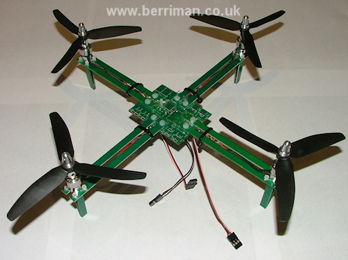
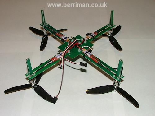
Over a year on and my interest has been rekindled. I decided to construct the frame and was all set to start milling the thin aluminium when I had the alternative idea of making it from thin strips of fibreglass PCB board I had spare. This is pretty light and very strong. The photos below show the assembled frame with the motors and speed controllers attached.


In order to ensure that the Quadcopter is stable, it is normal to use gyroscopes to detect rotation in 3 axis. Modern MEMS technology makes possible tiny gyroscopes formed on silicon substrates. These are packaged into a truly impressively small QFN surface mount package. Unfortunately unless you are buying a large number, they work out expensive to buy. Fortunately they are used in some low cost consumer items so with some knowledge they can be bought more cheaply. The SFC project is designed to use a gyro package from a Wii Motion-Plus module which are available for considerably less than the cost of a single gyro chip!

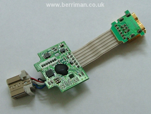
The photo above shows the small PCB removed from the Wii Motion-Plus enclosure. The biggest black blob is a “chip on board” device – these are used in mass produced devices to keep the cost down (the silicon die is mounted directly to the PCB) – and this is probably a microcontroller of some sort. The black square to the left is the Gyro package. Inside that small package (approx. 4mm square) are three gyroscopes, one in each orientation X, Y and Z.
The SFC project uses a specific Wii Motion-Plus board which has a Gyro chip which outputs three analogue signals proportional to rate. It turned out the device I bought does not have analogue outputs but uses I2C serial link instead. This chip is an ITG-3200 from Invensis and there are several datasheets on the manufacturer website. The I2C link provides access to the X, Y and Z rate values as 16 bit 2’s complement values.
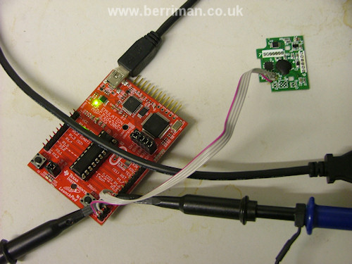
I plan to modify the SFC code so that it can work with the I2C version of the Wii Motion-Plus and therefore in order to check the board and develop the I2C code, I decided to connect the board to an MSP430 Launchpad.

The Gyro board requires 3.3V, SDA, SCL and GND connections. It has a base address of 0x68 with the LSB A0 configurable – on the Wii board it is hard wired to GND. The launchpad dev board is a composite of two USB devices, a debug interface and a virtual UART. I was therefore able to debug the code while streaming the data for X, Y and Z axis back to display on a terminal – Amazing that a £3 development board can be so useful!
I plan to give details of how to modify the Wii board and where to connect to the I2C signals in another post. I also hope to contribute my code modifications back to the original SFC project once tested.
Great looking quad so far. Are you using the 2553 chip?
-Thanh
Thanks for looking – Yes, I happened to have a 2553 chip in the Launchpad so just used that 🙂